Roland TR-505 IC1 “Sequencer Glitch” Bends
June 8th, 2010 | Published in Roland TR-505
We benders owe much to squidfanny for having the nards to bend IC1 (which resulted in possibly the raddest bend on the TR-505 ever) and for sharing what he learned.
I hope to clear up any confusion over how to bend IC1 here. In my opinion, this is a “must bend” for anyone tinkering with a TR-505. The pictures below should be rather self-explanatory, but if you’re having trouble, post your problem below and I’ll do my best to answer you.
This is a safe, easy bend for anyone with a little bending experience. I’ve found that any combination of these pins can be connected without any system crashes or resets. The only problem I’ve encountered so far is that, with certain combinations of (multiple) connections, all of the drums can become muted (but they bounce right back into the mix when unswitched), so a bit more experimentation is needed to weed out the little bugs.
It might be worth mentioning that my 505 is running program v1.1 (SN 690700 and up). I’m not sure this has any effect on the results of this bend.
IC1 (RAM) pins 1-8, 19, 22, and 23 connect to IC3 (CPU) pins 43-50 and 56-58. According to the Port Assignment chart on page 11 of the service manual, these pins are designated as “output, address bus” on the CPU (whatever that means). When these pins are connected, the sequencer glitches in a variety of ways, such as swapping drums, muting drums, swapping patterns, and stuttering triplets or 32nd notes, to only name a few. Neat-o.
But there’s more. Squidfanny found that this bend also effects the individual trigger outputs, and it might even be echoed through the MIDI output too (though I have not yet tested these two things).
I found that some pin connections seem to have no effect (such as 23/2, 23/7, and 23/8), while other connections appear to be redundant, so there’s still some sorting out to do.
You might want to avoid pin 24 on IC1. This is a (Vcc) power pin. I haven’t touched it.
As always, cross reference this information with the service manual and perform these bends at your own risk. You should assume that I’ve made some mistakes here…

Connect the blue dots...

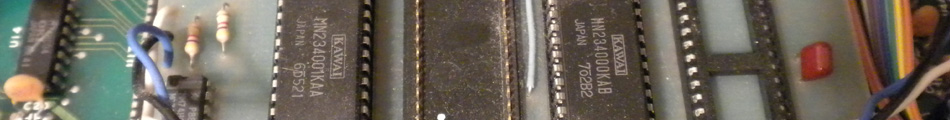
The traces between IC1 (RAM) and IC3 (CPU).

IC1 pin wiring from beneath the board. Bottom left wire is pin 1. Bottom right wire is pin 23. The pins marked with red (3 upper left and 5 upper right) connect to IC3 and are designated as "input, data bus" on the Port Assignment chart. I messed around with these connections a bit and I think they can be arranged to mute individual drums, but I didn't sort it out because I had several system crashes and resets, so I desoldered the wires.