Yamaha RX5 ROM Bending
May 8th, 2011 | Published in Yamaha RX5 | 6 Comments
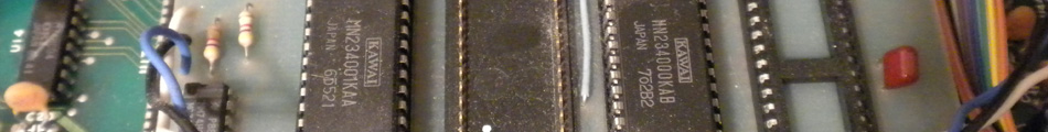
Here I’ll show you how to circuit bend the Yamaha RX5 drum machine. It’s standard circuit bending procedure: we’ll be connecting the pins of the RX5’s ROM chips to create some sounds it isn’t supposed to make. The ROM chips are IC45 & 46. Like the HR-16, both chips share the same connections so you can wire either of them.
Here’s a quick demo:
Bob Click’s Fantastic Light Parade
I owe a big thanks to my good friend Mike S. for this. He gave me this RX5 when I moved away ten years ago. Thanks duder, everything works now.
So the first step is to identify which ROM pins are “safe” for connection to one another. This usually means at least avoiding the power pins. A look at the schematic shows us which pins do what. I only wired the address and data pins. So far I’ve had no issues (i.e. crashing the machine), but do this at your own risk. I’ve played it pretty safe here, so if you’ve had luck using any of the other pins let us know.

Schematic showing which ROM pins do what. We'll be wiring the pins marked in blue.

Here's the view of the ROM on the PCB. There are two ROMs (IC45 & 46), but they share the same connections, so you can use whichever IC you want. Connect the dots...
I usually solder my wires to the bottom of the PCB, but in this case it made more sense to use the top of the IC due to the way the RX5 is assembled.

Rainbow wire soldered to the ROM. The wires run to an enclosure on the RX5's top panel, which houses the SPDT patch bay.
And here’s the completed RX5. I went with a SPDT switch patchbay for live use, but of course the design of your bending interface is up to you. A DB25 port and a handful of banana jacks might be handy. The next step is to install mute switches for each voice.

The finished circuit bent RX5 with 36 point SPDT patchbay. Oh, and that switch by the Accent 2 button is just a latch (for Accent 2).
January 7th, 2013at 10:30 pm(#)
hi,
could you give me a diagram and explanation for the modification rx5
send to my mail because the links do not work for my iMac
very grateful to you
March 15th, 2013at 3:37 pm(#)
hi, the mod looks do-able! but can’t seem
to open the tif of the schematic (‘not enough
memory’?!!!!). do you have it in other format?
or maybe link to other source(and service
manual, better look for that).
slightly confused by what is shown above,
so as much info as poss’, please!!
cheers
Dom
March 15th, 2013at 6:04 pm(#)
Hi Dom, thanks for dropping by. Please just download the .tif as a file to your computer instead of viewing it in your browser. I don’t have the file in another format, sorry.
Is there something specific in the post that confuses you? Let me know if I need to clarify anything. But you just solder wires to the ROM pins I’ve marked in blue and run them to an interface of your choice, which in this case is a bank of SPDT toggles.
March 17th, 2013at 9:35 am(#)
mmm, paintdotnet doesn’t like the tif. i’ll try something
else, then save it with other extension.
i see clearly the wiring to the eeprom; it is just the
other end, and which wires should switch where. or
doesn’t it matter? i haven’t bent any device before, just
fitted dinsync on a dr110, and i don’t want to fry my rx5!
also: did you use a D25 connector to bring all this out to
the box?
have you seen this? usb-programmable rx5 cart:
http://forum.anafrog.com/phpBB/viewtopic.php?f=36&t=9672
http://electro-music.com/forum/topic-56137.html
would a mix in audio input be reasonably easy? may seem
an odd idea, but useful for quick jam setup with something
else: just a stereo line in to the main mix.
March 17th, 2013at 2:07 pm(#)
Okay, apologies for the snag with the .tif. I’ll convert to another format and upload in the next few days.
Thanks for the link to the custom RX5 cart project! That looks really promising and I’m very interested in checking it out.
Good questions about the patchbay/bending interface. Sometimes I take the basics for granted. I’ll post a beginner’s guide to bending eventually, but here’s some info in the meantime:
1) Brief bending basics: When bending ROM chips like this, the idea is to make physical (wired) pin-to-pin connections between the ICs. We make connections where connections are not supposed to be made, thus resulting in garbled glitchy scrambled sounds as the chips can’t correctly sort out the data we’re feeding it. Essentially we’re ‘breaking’ the machine in a non-permanent, controlled manner. You can make as few or as many pin connections between the ICs as you like, with each combo of connections providing a different, initially unpredictable result.
The simplest way to start bending is to grab an insulated wire, touch one end of the wire to one of the IC’s pins, then touch the other end of the wire to another pin, and see what it sounds like. Once you know which pin connections make cool sounds, you’ll want to make these connections patchable (see #2 below).
There a couple pitfalls to watch out for, mainly that certain IC pins carry voltage and could potentially burn out the chip or other components if applied to the ‘wrong’ pin. Generally you’re safe if you just don’t use the power pins for bending. If in doubt, look up the data sheet for the chip in question and look at the pin out. It’ll show you which pins carry power voltage. In the case of the RX5, I’ve already identified the ‘safe’ pins above. Just use the pins marked with blue dots and you don’t have to worry about burning anything up. But this is within reason of course. I’ve had no problems bending with these pins, and I’ve been bending these pins on the RX5 for a long time. But that’s not to say there isn’t some unfortunate combination of connections that will reset, freeze, or damage your machine. This is the nature of circuit bending; it is inherently risky as you can never really be 100% sure of the results without a lot of experimentation. So as always, perform any bending at your own risk.
2) Regarding where the wires go after they’re soldered to the ROM pins: You have a few options, but I’ll keep it simple and use the toggle switch patchbay as an example.
Once you’ve soldered your wires to the ROM pins they need to connect to some sort of interface that allows you to switch the pin connections on and off (i.e. make & break the wired connections between pins). A toggle switch patchbay is a convenient way to achieve this.
I often use SPDT (single pole double throw) toggle switches. That means there are three lugs on the rear of the switch. You use one lug (let’s say the center lug) to ‘common’ all the toggles together (i.e. all of the center lugs of all the toggles are hard wired to one another). Then you connect one of the wires from a ROM pin to one of the unused toggle lugs. Now, when you turn a toggle on, a connection is made between the ROM pin and the common lug of all the other toggles, and the ROM pin will become connected to any other ROM pins that are currently toggled on. Thus, each toggle represents a physical connection to one of the ROM pins (for example, toggle #1 connects to ROM pin #1). If you want to connect to 25 ROM pins, you will need 25 toggle switches, one for each ROM pin you wish to make connections to.
Once all of the toggles are wired, you can make & break connections between pins by simply flipping the toggle on & off. Since the common connection of all of the toggles are wired together, you can ‘stack’ (i.e. make multiple) connections by turning on more than one toggle. Thus, the number of ROM pin connection combinations and resulting sounds is nearly unlimited.
And finally, using toggles is only one method (and somewhat limited at that) of connecting ROM pins together. When it comes to designing your bending interface you’re only limited by your imagination, so use whatever approach that best suits your needs. Some people use ‘bolt bays’ and alligator clips. Another option is to wire each ROM pin to a banana jack, then use banana cables to make the pin-to-pin connections. But this is a topic for another time…
March 17th, 2013at 2:11 pm(#)
I didn’t use a DB25 port on this RX5. The wires are run through the case below the breakout box. It’s all hard wired so there’s no fiddling with extra wires or cables.
A mix to the stereo outs should be pretty easy. You’ll just need to solder your input wires directly to the main output jacks on the PCB. You’ll probably want to place an attenuation pot in series with the input so you can control the output volume.